About two weeks ago, my Alpin 100 suddenly failed whilst transmitting. Shutdown with error 52. The manual stated that the high voltage was less than 1500 V or over 3300 V.
I tried to restart and immediately went to the HV menu, the voltage was about 2100 V, which was much lower than the expected 2800 V. Not much later, it went down again with error 34. Same error description. After waiting for half an hour, I tried again, but this time immediately error 23, which says HV less than 350 V for more than 120 ms.
As I was going to my QTH in France, it had to wait until I returned. Being back home, I started with having a good look at the schematic diagram. Unfortunately, this is not very detailed and left some guesswork, which I hate. Searching the internet was not rendering much additional information.
I knew that the Alpin resembles the Acom 1000 and after some searching, Acom schematics were found with a bit more detail. But it was clear that the power supplies differ considerably. It took me quite a bit of time to figure out how everything was hooked up and how it supposedly works.
I started with checking the rectifier, which I suspected initially. Measured diodes and capacitors for any short or open circuit. All diodes were conducting one way (as they should…) and it was also established that the resistance across the capacitors matched that of the bleeder resistors. Hmm, so the rectifier seemed to be OK, with low voltage of course.
Plan of attack
So, I had another look at the diagrams and the actual circuit to see if I could isolate it from the rest and try if the HV supply was working under normal operating conditions. Luckily, I have a variable mains transformer, so I decided to start testing with a low voltage and to increase it afterwards. For safety, I created a mains lead with a light bulb in series, to add protection. I also reasoned that the bulb would show possible instability immediately.
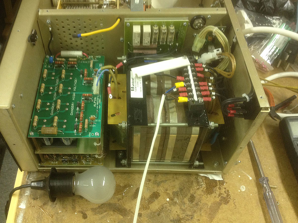
Alipin 100 test setup (picture taken after faulty resistor replaced)
The picture shows the test setup. To the right, two connectors are visible, one with nine pins and one with two. I determined that the two pin connector connects to the filament of the valve and the nine pin connector wires are for screen and grid voltages (and some more).
For the initial test, I disconnected everything from the transformer, except the output to the rectifier. The 230 V input wires were put aside and replaced with a mains cable to feed it from the variable transformer.
The yellow HV lead to the RF deck (top left) was disconnected too, so only a transformer and rectifier were active.
With a low primary voltage, about 30 V DC appeared at the output to the RF deck. Increasing the voltage did not reveal any trouble.
My old analogue multimeter is limited to 1.2 kV DC or AC, so I did not go above 1.2 kV DC. This corresponded to nearly 500 V AC from the transformer. Thus, at half the operating voltage, all appeared to be functioning well. It was already late, so I decided to quit and continue the next morning.
Safety first
Working with high voltages is definitely not my favourite activity. One mistake or a distraction can be lethal. So my approach is not to poke around with multimeter test leads, tools or the like. I prefer to prepare a measurement setup and after all is connected and everything checked, power is applied to observe readings or other phenomena to look at. Before moving on to another step, power is disconnected completely and a pause is taken to discharge the capacitors via the bleeders. After the pause, I check the DC voltage to be absolutely safe.
I also make notes and photographs to prevent mistakes when (re)connecting.
Preparing for the next test with operating conditions
The transformer and rectifier looked to be OK, although I could not rule out that something could break down at higher voltages. It was decided to restore all connections, put the cover back on and have another try. No luck, error 23 again. Hmm. Strange. Could it be that the relays of the rush on protection were not conducting properly?
So back to the variable transformer with light bulb to test the HV supply again, this time with the filament on. The nine pin connector was left open. The yellow HV lead also disconnected. I wanted to simulate the rush in phase with a resistor in series with the mains supply. I assumed that the additional load of the filament power could keep the HV low. The light bulb should indicate this clearly.
Voltage divider
Because my digital multimeter voltage limit is 1 kV, I decided to use the voltage divider on the rectifier board. This divider consists of four 1 M Ohm resistors in series. At the ground end, a low value resistor connects to ground and one can see that this junction goes to the control board for measurement of the high voltage. With a low voltage applied to the primary of the transformer, I first checked the reading between the first and second resistor, which should be about a quarter of the HV output.
But nothing on the meter. I checked the leads of the other resistors and found that the second one was open. The protection circuit did not see a voltage at all and misinterpreted this as a fault condition.
In my junk box, I found 270 k Ohm quarter Watt resistors. Four in series would come close to the required Ohmic value and the power rating should be adequate. 3 kV divided by 4 M Ohm results in about 0.7 mA, which implies about 0.7 Watts to be dissipated in the four 270 k resistors. Should work.
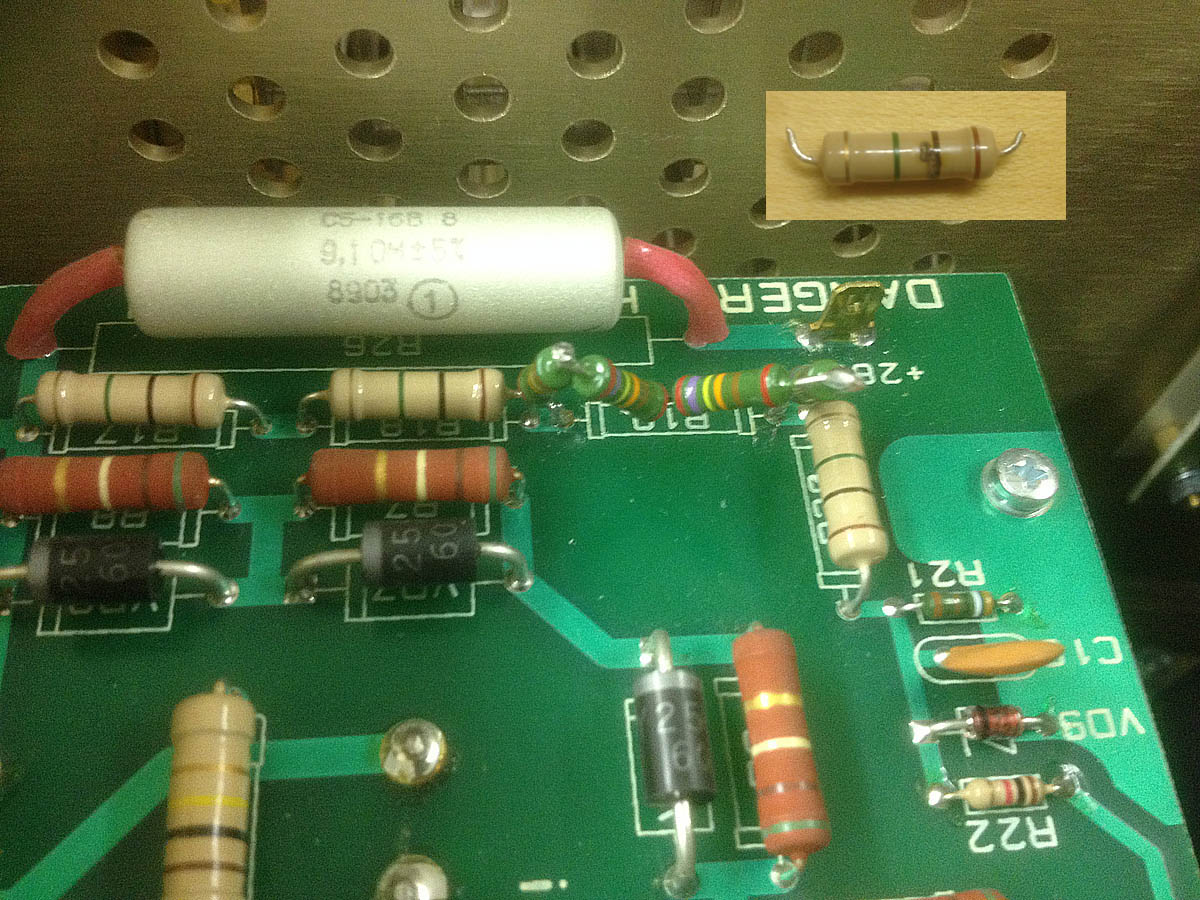
HV rectifier with replacement resistors and the faulty one (inset)
The picture shows the four resistors and the faulty one that was removed, with visible damage in the inset (which was not seen when visually inspecting, because it was at the side of the RF deck).
For those who don’t like the looks: I will replace all four 1 M Ohm resistors, maybe even with eight, to reduce the voltage across each resistor.
The result
After reconnecting everything, the cover was put back on and the power button was pushed. Yes, this time the amp started as usual. The countdown from 2:30 to zero was running.
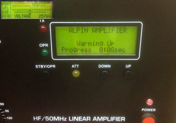
Warmup after repair with HV diplay (inset)
The HV reading was immediately selected and the inset shows that it was well within range. It reads a bit lower than before, but I take that for granted.
Postscript
It has to be said that I considered a measurement error of the protection circuit to be possible, but far fetched. The voltage divider fooled me and if I had a multimeter with a probe for higher voltages, I would not have used the divider for my own measurement. So, I could have been searching much longer and in the wrong direction.
This illustrates that it is imperative to work systematically and to not take things for granted!
Update 13 December 2020
After getting a bunch of resistors the day before, it was time to replace the for 270 k Ohm resistors. I decided to replace all four 1 M Ohm resistors. The power rating of new ones is higher than the original ones, but they fitted on the board nicely. The rectifier board was removed with ease. It just took a bit of fiddling with the resistor leads to get them into the holes in the printed circuit board. Measurements confirmed the required 4 M Ohm. Time for the board to be put back and have a go. The high voltage now read nearly 2.8 kV, which I remember to be close to what was seen before.
The RF tests passed and I left it standby for half an hour. I declared it to be fit to return to the operating position. Time will tell how it plays out, but it would surprise me if the voltage divider fails again. If it does, plan B will come into action: replace the 1 M resistors with duo’s of smaller values, to decrease the voltage drop across each of them.