Over time, items were added to the inventory of measurement instruments. But it all started with some simple things, because professional instruments were way out of reach at the time I was licensed in 1976. We had to cope with uncomplicated equipment to be able to “guesstimate” what we were doing.
The grid dipper
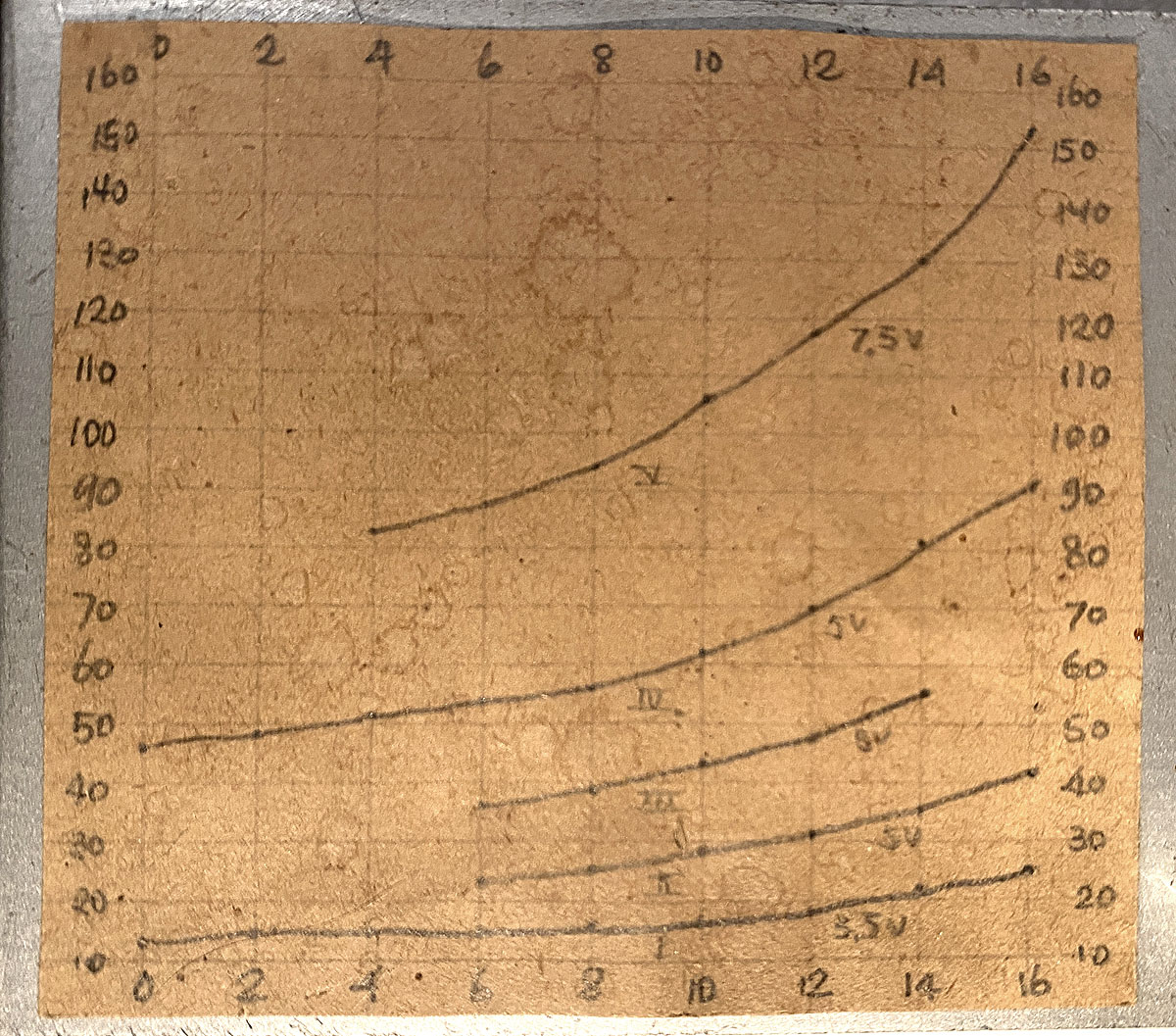
One of the first things to measure with, was a transistor dipper with a number of coils, which were wound on the plastic cap of RCA plugs. A chart showed the frequencies where it oscillated.
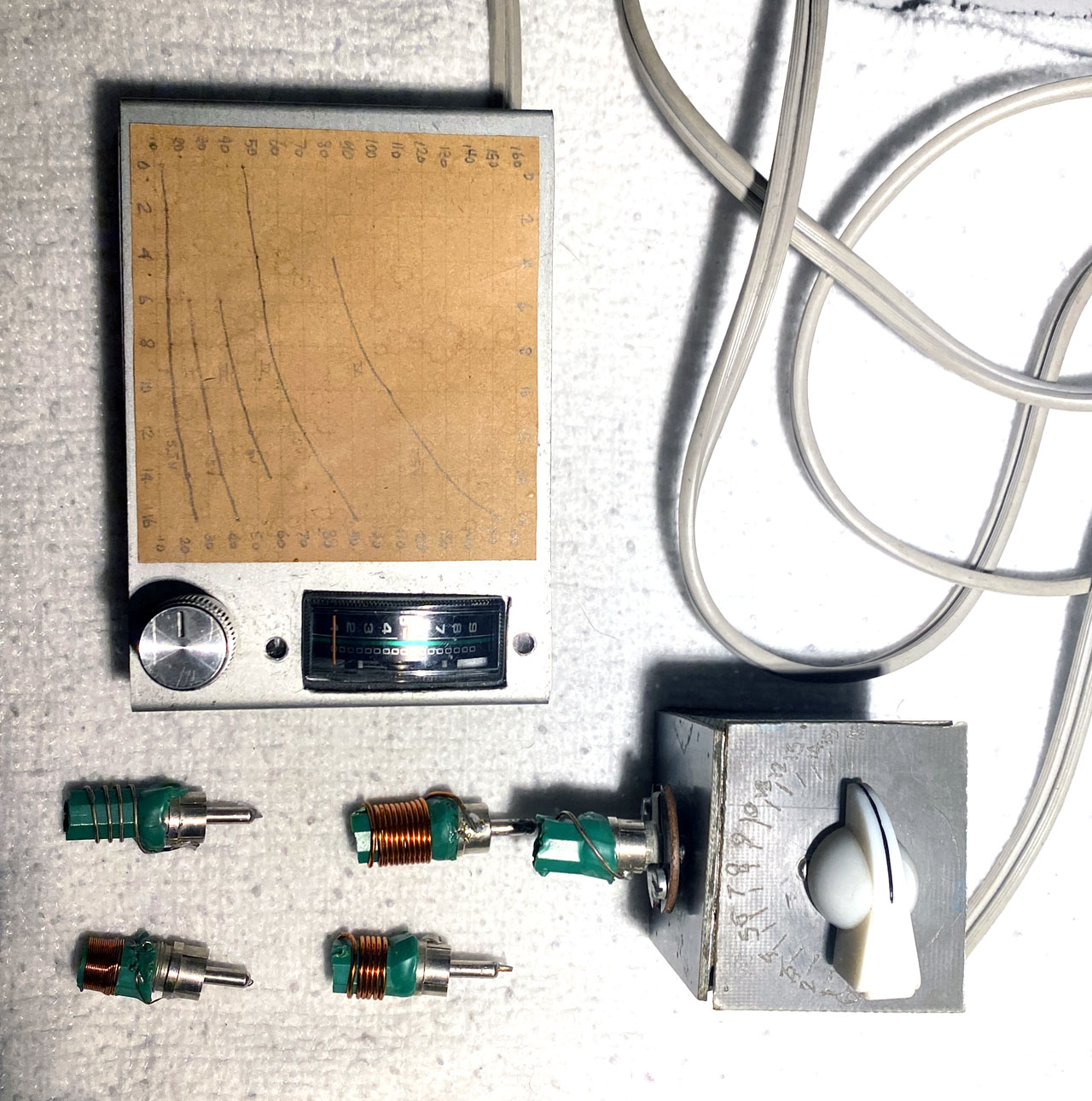
The dipper was made of two separate parts, one box for the battery, meter and potentiometer (to adjust the reading on the meter) and the other part was the actual oscillator, in a box of printed circuit board. With the small box, it was easier to “poke” into circuits. Many commercial dippers were quite bulky and less handy. Dippers are usually good enough to get tuned circuits within the desired range and they can also be used as a simple signal generator.
The dipper was checked and even after about 45 years, it worked fine and the frequencies on the chart were still correct. For a small investment, a simple instrument can be created and it could be a nice little learning project.
Installing cable-TV systems
In 1982, I started working as a technician for a small cable-TV installing company. The networks were adjusted using dedicated level meters which were in fact small television receivers with specific measurement capabilities. We did not have spectrum analysers.
A job was offered to me in 1983 to start as a consultant. It was a small company and cable-TV operators hired us to inspect and commission newly built networks. Because spectrum analysers were expensive, they had a rather high standing and thus, a Takeda Riken 4132 was at my disposal. It ranges up to 1 GHz which was sufficient for cable-TV networks.
It must have been October 1983, when satellite television was introduced after the successful launch of the ECS-1 satellite, carrying Sky Channel and Super Channel. The cable-TV operators were competing amongst each other to try to be the first to add these two channels to their network and my job was to lead the project in Maastricht. The installation looked like this:
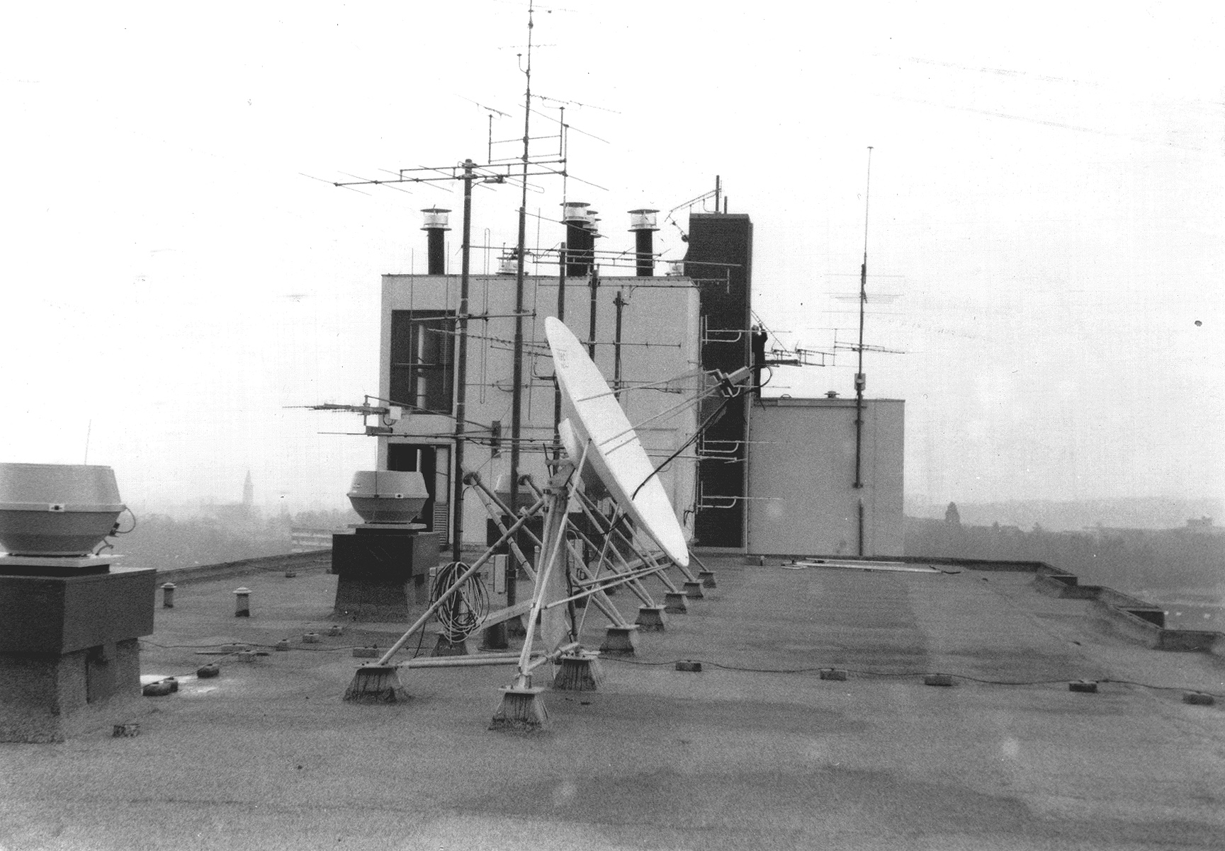
We were assisted by the supplier of the receiving equipment because it was obvious that our 1 GHz analyser was not suitable for this kind of installations. A frequency range up to about 1.8 GHz was needed.
It did not take very long before a new spectrum analyser was acquired. It was an Advantest TR 4131. The frequency range up to 3.5 GHz was more than adequate for checking satellite television IF signals. Although it is not phase locked and its stability is modest, it was easy to find the satellite beacons. I kept notes of the beacon C/N values of the receiving sites I commissioned, so I was able to verify if reception was on par.
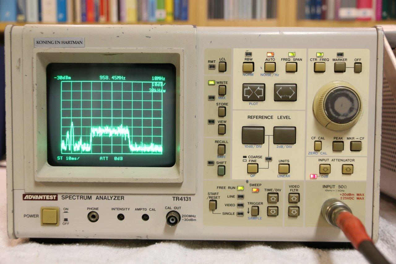 Not too long ago, I stumbled upon a TR 4131 (see the picture). It was gathering dust and it was not well kept. It took over half a day of cleaning to get it into a reasonable visual state. It also was a fair amount of work to restore its interior functioning to an acceptable level. Not completely done yet, the frequency jumps somewhat when changing span/bandwidth in auto mode, which I guess needs some alignment. A service manual lacks and I prefer to know what I am doing, so I will leave these flaws for the time being. In general, it is functioning reasonably well now.
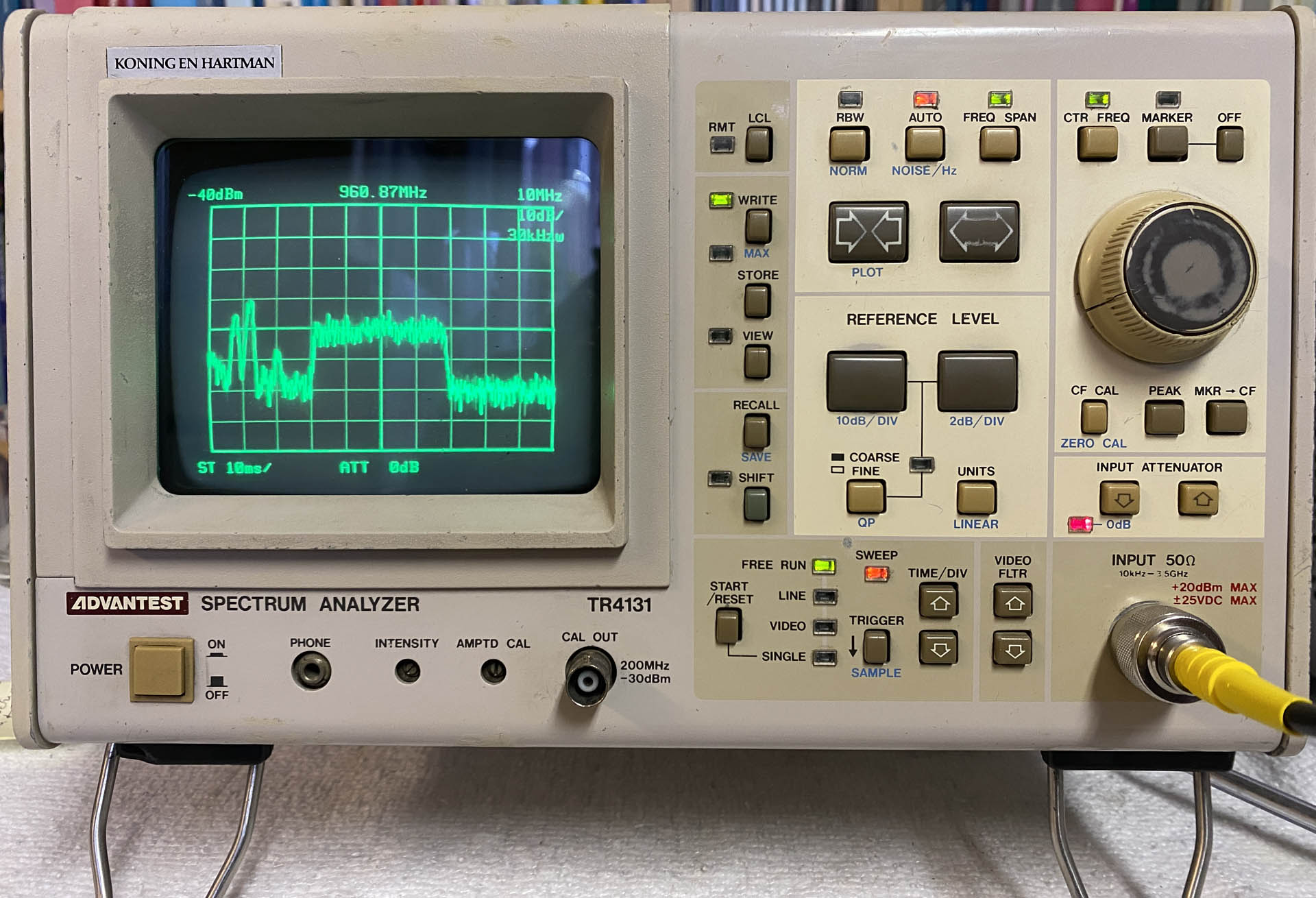
Here is another picture, after the exterior had an update with some paint.
Self employed
Late 1988, I decided to establish my own company. Soon, I was approached to develop software for the Cable-TV division of Philips. At the time, Philips was one of the leading suppliers of Cable-TV equipment. A contract to replace equipment for the network in Amsterdam was won by Philips. Satellite television led to the need to increase the capacity of the Cable-TV networks. Several hundred nodes had to be upgraded, along with the distribution network. A comprehensive measurement report of the nodes was required. Various parameters had to be tested and the results documented, like noise figure, amplitude flatness and group delay characteristics.
I was asked to develop software for automated testing and it was a very challenging project.
Some pictures were made of the setup as well as a screenshot of one of the first test measurements.
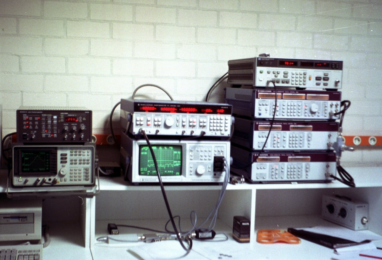
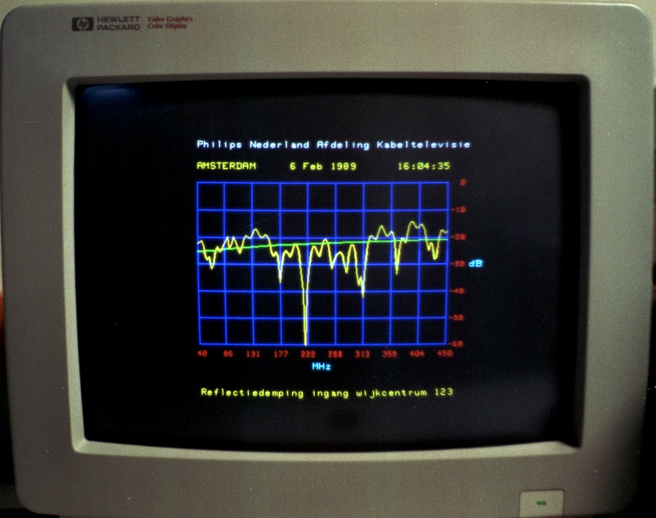
The instruments were connected via HP-IB (GP-IB). The Rohde & Schwarz ZAS + SWP were used for transmission, return loss and group delay measurements. Intermodulation properties were established with R&S SMG/SMX generators and the HP spectrum analyser. Noise figure was measured with the HP 8970B. Measurements were shown with limit masks, to confirm that requirements were met.
The software was a story by itself. Philips already bought a HP computer with so called HP-IB controller, which was in fact a second computer on a ISA card running HP Basic.
Their department wanted to develop the software themselves, but it failed whilst time was running out. I accepted the challenge. About three months later, the project was in its finishing stage. All required measurements were operational and reports could be printed. Some tweaks followed later, but the goal had been achieved.
Since then, 35 years have passed and much has changed. But even with modern environments, 3 months to develop an entire measurement suite would be hard to beat.
The project laid the groundwork for my involvement in software for test and measurement.
Here is an article about a new outfit for the HP 8568B spectrum analyser: New outfit for men over 40 
(Part 2 follows, but unsure when…)