Back on the air late 2015
In 2007, I moved to the current QTH and did not put up antennas. The announcement of permits for 60 metres “sparked the sparks” again.
December 2015
During November 2015, the 60 meter station was put together, awaiting the permissions for 60 meter to become valid.
On 60 meters, I am using up to 100 Watts on SSB or CW. With digital modes (mainly JT-65 or JT-9), the power is mostly reduced to 50 Watts, avoiding stress to the equipment. Note: On April 1st 2017, our allocation was reduced to the WRC 15/15 allocation (15 kHz/15W).
Recently, I rearranged a home made QRP transceiver for 5 MHz, but this project needs a bit more time. When conditions permit, just a few Watts are sufficient to make a QSO, especially with weak signal modes like JT65 or JT9. Most WSPR beacons (see wsprnet.org and select 60 meters) operate with less than 5 Watts. I have seen numerous spots with distances well above 15,000 km.
The 60 meter antenna is an inverted V dipole (full length), the top is nearly 10 meters above ground, the legs sloping down to about 7 meters AGL.
A MFJ fibreglass mast is mounted at the wall, with a tilt mount. Ropes with pulleys hold the mast against a wooden block on the wall. Very simple, but effective.
The dipole is fed via a balun, better known as “ugly balun” (more info: here). This is a coil of coax, wound around a PVC pipe. The bottom end has a smaller cap, glued into the larger one, to keep the connector dry. At the top, the inner conductor and shield of the coax are connected to the red and black wire via screws that pass though the PVC pipe.
It is important to keep the capacity between antenna side and feeder as low as possible, so keep the balun away from conducting surfaces.
Here are some pictures:
-
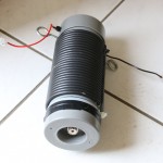
- Ugly balun
-
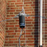
- After assembly
-
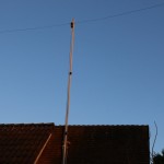
- Fibreglass mast with antenna
Update March 2016
Man made noise (see article) is a serious problem for many of us and unfortunately, this is true at my location. Two of the worst sources I suspect are a TV set that is causing S9 noise and a solar panel system which causes 50 Hertz spike noise (similar to power line noise). I tried to reduce it by installing a reflector behind the dipole, with a relay in the centre, to switch it on or off. It helps a bit, but not completely.
Next to the dipole, further away from the noise sources, I put up a vertical, but this was not successful. It picks up much more man made noise and when checking my signal on web SDR receivers, it does not outperform the dipole when transmitting.
But when experimenting with it, I found that I can use the vertical to cancel out noise. It appeared that the noise varied when connecting or disconnecting the coax feeder of the vertical. So I decided to add some lengths of coax from the cable box and I could find lengths where the noise nulled out. So, I now use a selected length of the coax line and with an antenna tuner in the shack, I can tune to the point where the noise is cancelled out. When the frequency is changed (for example to 5259.5, still trying hard to receive ZS6EZ…), I simply adjust the tuner. So, the vertical is a weird passive noise suppression system
My guess is that the vertical receives the noise and reflects it back to the dipole with 180 degrees phase difference and the right amplitude to cancel the noise out.
This works better than any separate receiving antenna that I tried, like loops, terminated loops and the like.
Update May 2016
With the start of the sporadic-E season, I wanted to put up an antenna for 6 meters. The fibreglass mast restricts the permissible load, so I took a part of the 6 element yagi and turned that into a 3 element beam. I wanted to reduce the wind load from the 60 meter dipole, so I chose a Diamond 1:1 balun and thinner wire, which was used for army telephone lines, with steel and copper wire in it. It weighs next to nothing.
It seems that the noise level on 60 meters is quite low, even without the compensating vertical as described above. Time will tell how it performs for transmitting, but initial QSO’s indicate that it is just as good as the dipole with the ugly balun. It could be that with the Diamond 1:1 balun, the dipole is better balanced. Anyway, as long as it is good, I should not complain:-)
On 6 meters, the Chinese electronic crap is loudly audible. Wideband noise, power line like noise and impulse trains from a power line transmission system about 100 metres away are disgusting examples, indicating that the European EMC directives are way too lenient. Remember that the distance to the suspected sources is well over 30 meters!
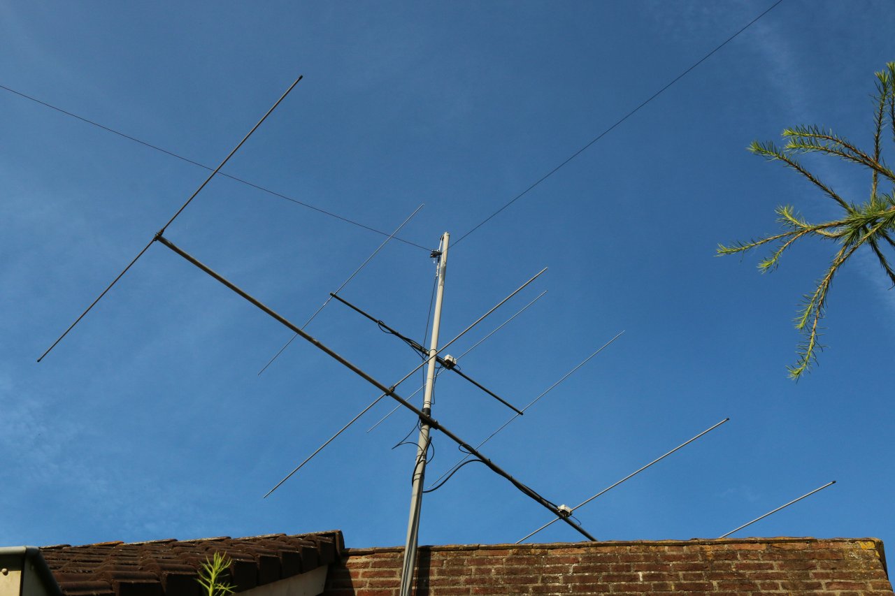
A picture of the setup below:
PA2S antenna – May 2016
Update July 2016: 4 meters added
The first weekend of July, I finished my 4 meters transverter. My good old 6 meters transverter, originally built in 1987, was just gathering dust. Not without emotions, though, because I worked about 146 entities with it.
But modern times with DSP transceivers took over…
The modification took a couple of evenings and it passes the tests, so to say. Some tweaking has to be done, but QRV on 4!
Output about 5 Watts, antenna is a 3 element yagi.
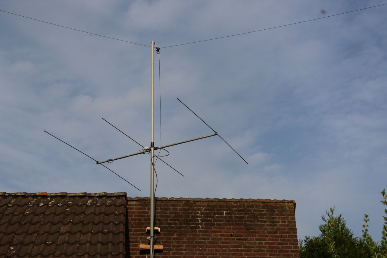
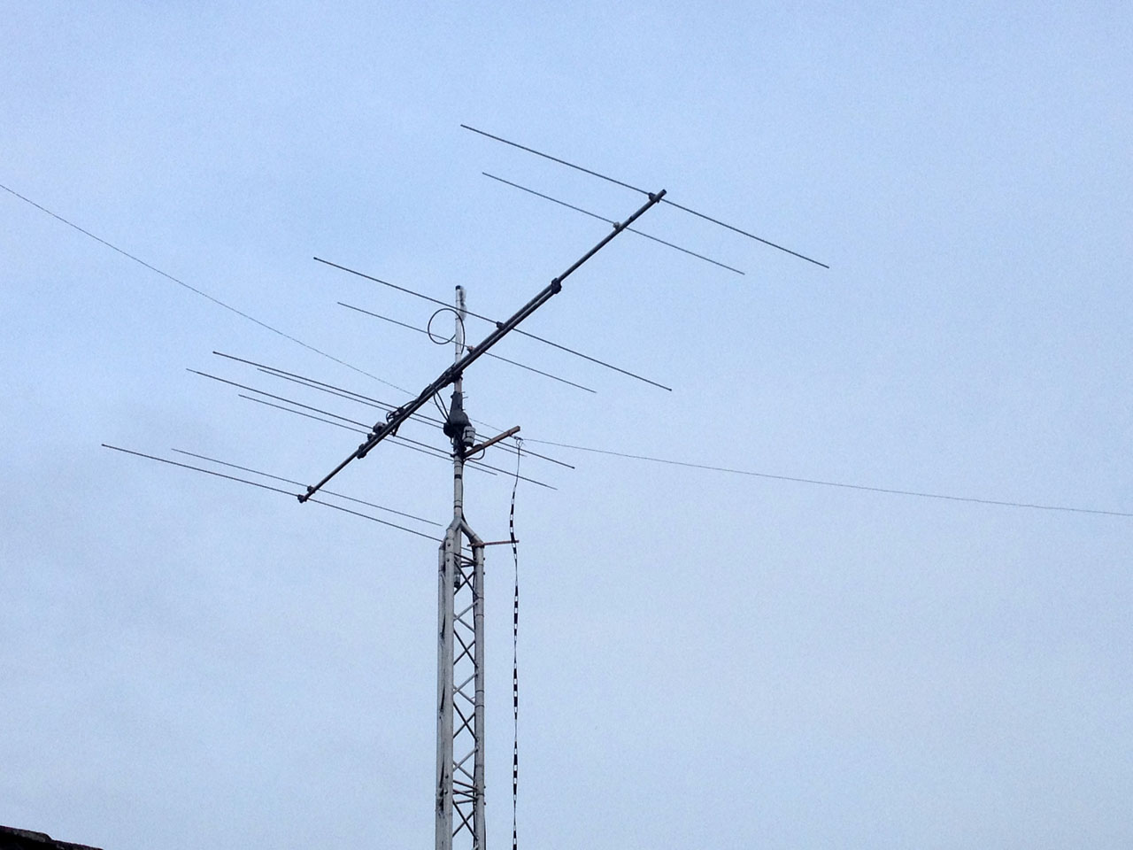
This is the antenna setup (the 6 meter yagi is longer now, but still too low).
PA2S Antenna July 2016 – Top to bottom: 60 meter dipole, 70 MHz 3 el. and 50 MHz 4 el. yagi.
Update August 2016: small tower installed, 4 m station improved
As long as amateur radio blood flows, it will put pressure on the performance of the station… thus a little tower was acquired and modified. The 4 meter antenna was changed from 3 to 4 elements, boom length is about 2.8 m. It performs noticeably better than the 3 elements, which I did not expect, as the difference in gain is small. Apparently, the overall noise level is somewhat lower because of the improved directivity. Of course, the added height helps a bit as well. I can now hear the LX1FOUR beacon 24/7. Usually weak, but always there.
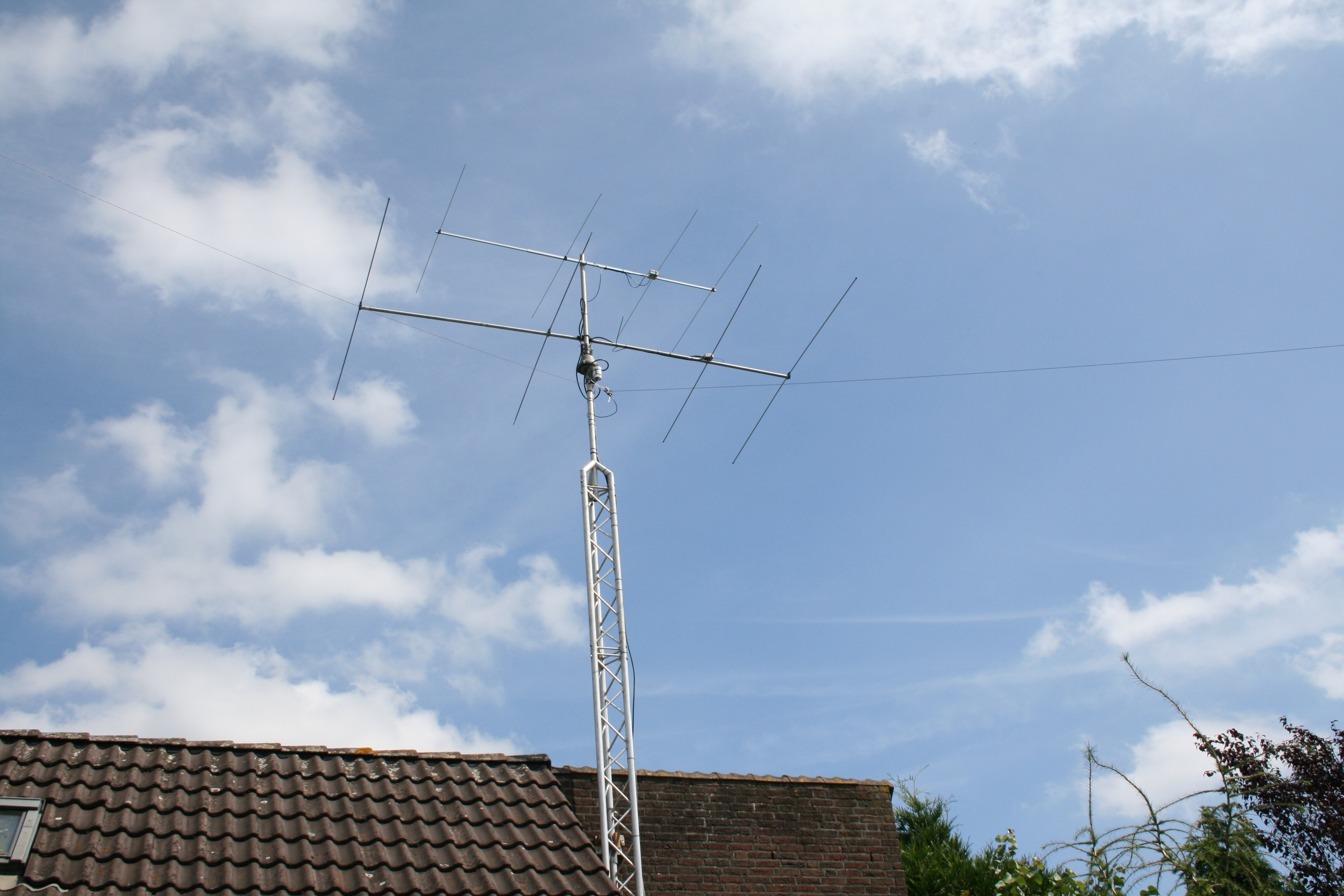
PA2S antenna August 2016
During August, the PA for 70 MHz was put into service, increasing power output with roughly 10 dB. It was nice to be able to work a couple of new ones during the Perseids meteor shower.
September 2016
In September, the 6 meter antenna was taken down and replaced with a small yagi for 70 cm. I will try to fix my transverter for 70 cm and may take part in the October UHF contest.
October 2016
The 70 cm contest was not really a success, because of the low activity. Here is a write-up: 70 cm contest 2016.
After the contest, the 70 cm antenna was replaced with a 3 elements yagi for 6 m, the “winter version”. Some meteor scatter QSOs were made.
November 2016
The latest modification is the replacement of the 60 m dipole. I was looking for a multiband solution. After quite a bit of reading, I decided to make a doublet with a balanced feeder and tuner. It was used during the 2016 CQWW CW contest and it worked very well. Nearly 100 DXCC entities worked with 100 Watts.
Balanced feeder line to doublet
On 60 m, the performance of the doublet seems to be a tad better than the dipole. The tuner is an old TenTec 229B tuner. I had to replace the fixed capacitors, because they were unstable. I found Russian doorknob capacitors with 12 kV rating and now it is rock solid.
A separate article shows the modification. The front panel lighting was replaced as well, it now has contemporary LED lighting (without noise, being fed from a 12 V linear power supply).
April 2017
Unfortunately, from April 1st 2017 onwards, the 60 m permissions in The Netherlands were reduced to the WRC15/15 allocation. So, the output of the station had to be adjusted:-(
The antennas for 6 and 4 metres were taken down during the winter period. The 4 metre antenna was put together rather hasty and needed an upgrade anyway. Some articles about dual band 6/4 metre antennas inspired me to have a closer look. One of the reported drawbacks of dual band antennas is the vertical radiation pattern. Often, only horizontal diagrams are considered, but these days, man made noise poses a serious problem. Most of the designs I came across, suffered from bad vertical side lobes. I was just about to give up when I stumbled upon the YU7EF design, which had a better pattern. So I decided to put it together. A separate article reports about the antenna. It is difficult to judge how it performs in real terms, but the first impressions are positive. A comparison with a Tonna is planned and I also intend to compare it with the former 4 metre yagi.
50/70 MHz dual band yagi
Various changes until late 2023.
The dual band yagi worked OK but I was not entirely convinced of its performance. I reverted to separate 6 and 4 metre yagi antennas later on. Because 6 and 4 are very quiet during the winter months and I was focusing on 60 metres, the yagi was removed and a fibre glass mast was out up late 2017, supported by the tower, in order to raise the apex of the 60 m antenna from about 10 to 15 m AGL. Simulations suggested a slight improvement of gain at low angles but the impression was that the actual difference was larger than that.
Summer 2018
I assume that the increased height helped to have less impact from neighbouring houses, which may absorb the EM field. During the summer months, the yagi was put back. In September 2018, I tested a rotary dipole (with coils at the centre) to receive with on 60 metres. It was a bit so-so, partly because of mutual coupling with the dipole.
February 2019
A second QTH in France was found during 2018 and the contract was finalised in February 2019. This meant that a lot of time was going to be spent on home improvement over there. Activity was quite low in 2019 at home.
Spring 2020
I wanted to be more active on VHF and UHF and found a used Icom 7100, A 144 MHz antenna was acquired and for some time, I was found on 2 m and 70 cm. But it must be said that activity was very low. After the CW requirement was lifted to operate on HF, a lot of former VHF/UHF only licensees moved to the HF bands and even during contests, it was a lot of hard work to get a few handful of stations in the log. 60 m was hot and I was very active on that band.
Autumn 2021
60 was my focal point, but in November 2021, a Fritzel three band dipole was installed for the CQWW CW contest. The dipole outperformed the multi band antenna on 15 and 10 m, but 20 was not much different. After the contest, I continued making some contacts on 10 m, but I have to admit that the traditional HF bands never appealed to me. Why copy what everyone has done before? Why calling DXpeditions like mad (read: pressing function buttons to send your callsign endlessly)? Even 60 m is losing it’s charm of being new and is becoming a regular HF band with the “usual suspects” trying to work themselves to the top of lists etc. But my challenge is to work DX with my modest station (and 10-15 dB higher noise level than it would be at a quiet location).
Spring 2023
Much time was spent on the house in France and I also enjoyed 60 m a lot over there, because the French authorities finally gave access to 60 m. At home, the 3 band dipole was replaced by the 6 m antenna. A test was done with the 6 m antenna (reduced to 3 elements) with the 60 m dipole suspended just below.
Two pieces of rope hold the dipole wires at some distance from the original feed point. This was very simple and non destructive, so reverting was easy. The ropes were long enough to be twisted around the mast and this worked pretty well in fact. The 3 element Yagi was optimised for minimum sidelobes and that was quite satisfactory too. The boom was about 2 m long and the whole structure lightweight and with limited wind loading.
In the Netherlands, the law is very restrictive and the maximum height is 5 metres above the point where the mast starts protruding above the building at that point. I am a bit lucky in the sense that the roof is one-sided at that point. The 5 m rule applies to the rooftop (which is just 5 m AGL). Nevertheless, it worked reasonably well.
Spring 2025
Man made noise, caused by solar (micro)inverters and LED lighting increased considerably. To the east, background noise on 6 metres has increased dramatically. When connecting the antenna, the noise level goes up roughly 30 dB and reception of weak signals is effectively over. In other directions, the noise level is not much less. During the dark hours, the solar inverter noise is replaced by QRM from LED garden lighting.
See this page for details and a simulation of the situation if we still had analogue television. I wish we still had it, because it would have protected us. The man made noise would have caused very many complaints and had put pressure on EMC requirements.
The solar inverters and optimisers also affect reception on the HF bands. On 60 metres, the S meter goes up to over S9 on sunny days. Back in 2015, it was around S6 to S7, which was already high. On a similar antenna configuration, the background noise level is about S4 in rural France.
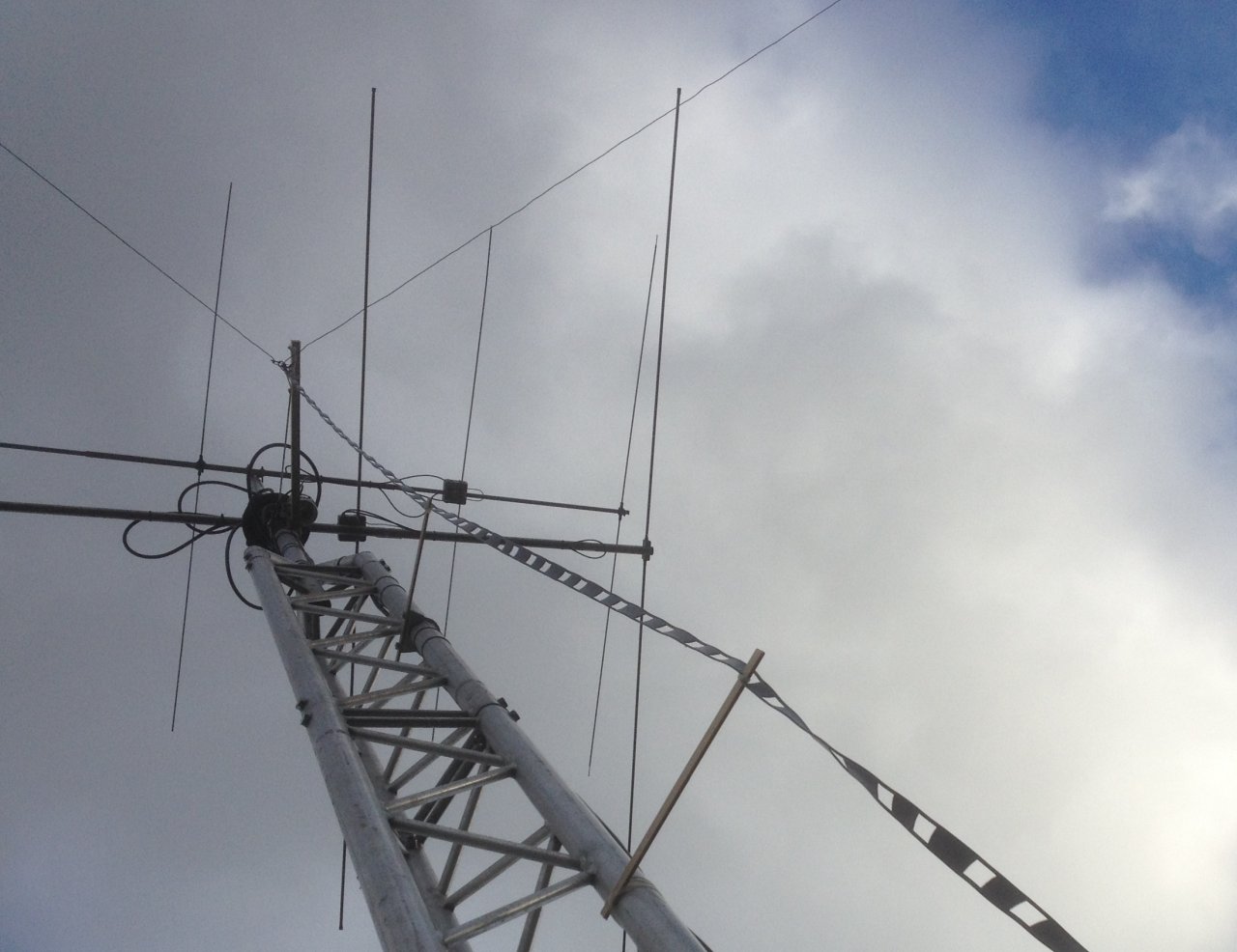
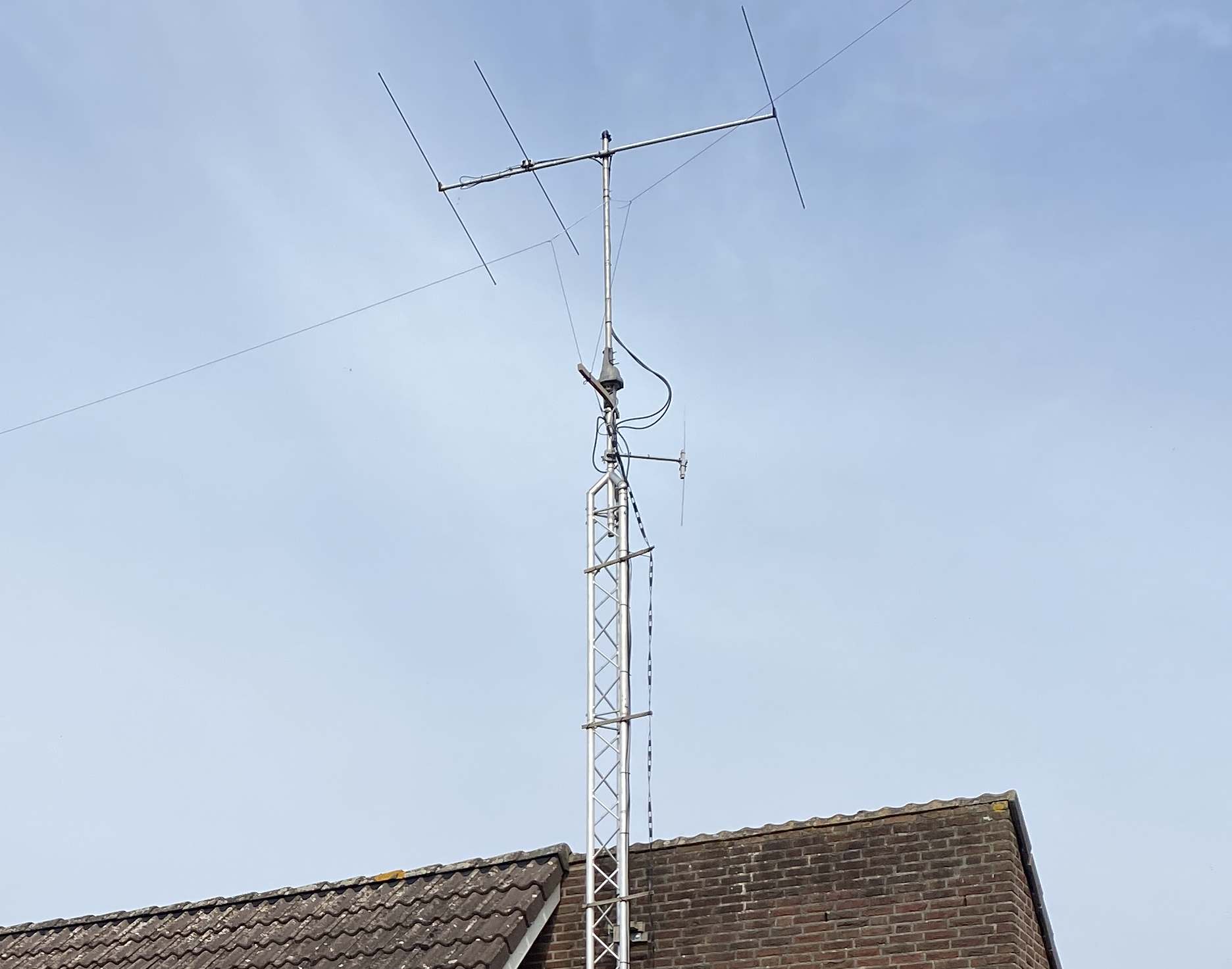
The antenna configuration was changed a few times. The May 2025 situation can be seen on the picture below.
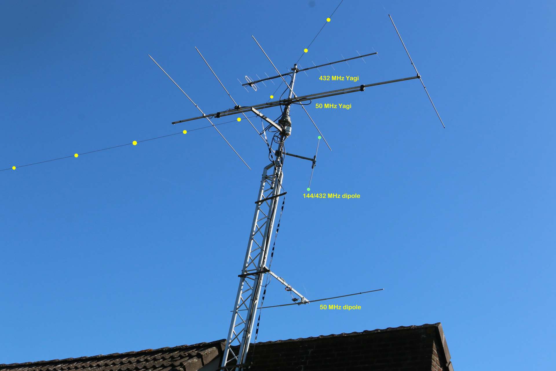
May 2025 antenna