Not too long ago, a pre-owned Icom IC-7100 was acquired, as a replacement for the IC-706 mk II. Although the 706 is a small, versatile and a “value for money” little devil, it has its habits.
On 2 metres, the IC-706 frequency drift is very annoying and way too much for narrowband digital modes. Even in CW, the drift is clearly noticeable and resembles ancient equipment. One could try to get a high stability oscillator for the 706, but that would not fix some other disadvantages, like the limited IF filter stop band attenuation and other drawbacks, when compared with more modern equipment with DSP and USB interfaces. It did not take very long to find a 7100.
The IC-7100 brochure states 0.5 ppm with a TCXO, compared with 5 ppm for the IC-706. The most annoying problem of the 706 is frequency drift between transmit/receive cycles. It it was obvious that temperature variations caused considerable drift. FT8 was simply impossible with the 706.
The first impression of the 7100 was that the stability seemed good enough for FT8, both on 144 and 432 MHz. After initial drifting and slant waterfalls, a few minutes after power on, FT8 signals became stable. A number of QSO’s were made and it looked good.
Dutch digital activity contest on April 8th 2020
During this contest on 432 MHz, I noticed that some of my replies to CQ’s seemed to go unnoticed. Some stations were rather strong (+ reports) and I wondered if my transmissions were decoded at all. So I wanted to have a closer look at things.
FT8 has a tone spacing of nearly 6 Hz and one would expect that drifts should be no more than half the spacing or so. After a bit of searching, I found a statement of K1JT about frequency drifts with FT8, confirming the 3 Hz drift limit:
There will be little sensitivity loss for frequency drifts up to ~3 Hz over a 12.6 s transmission. Things will degrade significantly if the drift is much larger.
With sufficient motivation, it would not be very difficult to add “AFC” capability to a specialized FT8 decoder. WSJT-X already includes such features for JT65 and JT9.
Time for setting up some measurements (all done on 70 centimetres).
Drift in RX mode
The first experiment was to measure the drift in receive mode. A LPRO 101 Rubidium reference (10 MHz output) was connected to the 7100 and the frequency was tuned to just under 430 MHz. The Rubidium oscillator generates a sine wave but weak harmonics were audible, albeit that the spectrum is a bit noisy.
The audio from the 7100 (USB) was fed to Spectrum Lab to observe the signal of the 10 MHz (43rd harmonic) source on an audio spectrogram.
The first picture (click to enlarge) shows the drift from 5 minutes after switching on until about 35 minutes later. The dial frequency was 1000 Hz below 430.0 MHz so that 1000 Hz audio would be the harmonic of the 10 MHz reference. Initially, the frequency was about 70 Hz off and after about 5 minutes, the error was about 40 Hz. An error of 0.5 ppm corresponds to 215 Hz, so this is well within the specification.
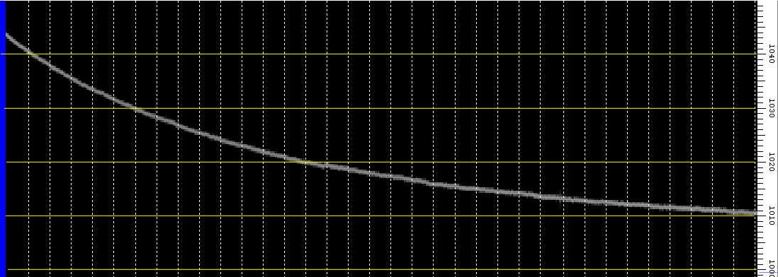
IC 7100 receiving Rubidium reference after switch on
TX drift
The next graph shows a second measurement, again receiving the Rubidium reference. This time, I used WSJT-X to transmit carriers (using the tune function). A little multiplier was made with a wideband amplifier, driven into saturation, to obtain stronger harmonics of the 10 MHz signal. The frequency setting was a bit different, the correct frequency should this time be around 140 Hz. The left part shows the warm-up period, which was similar to the first test. At about 22:24 transmissions were started (yellow 1 on the graph). During transmission, audio was absent and not visible.
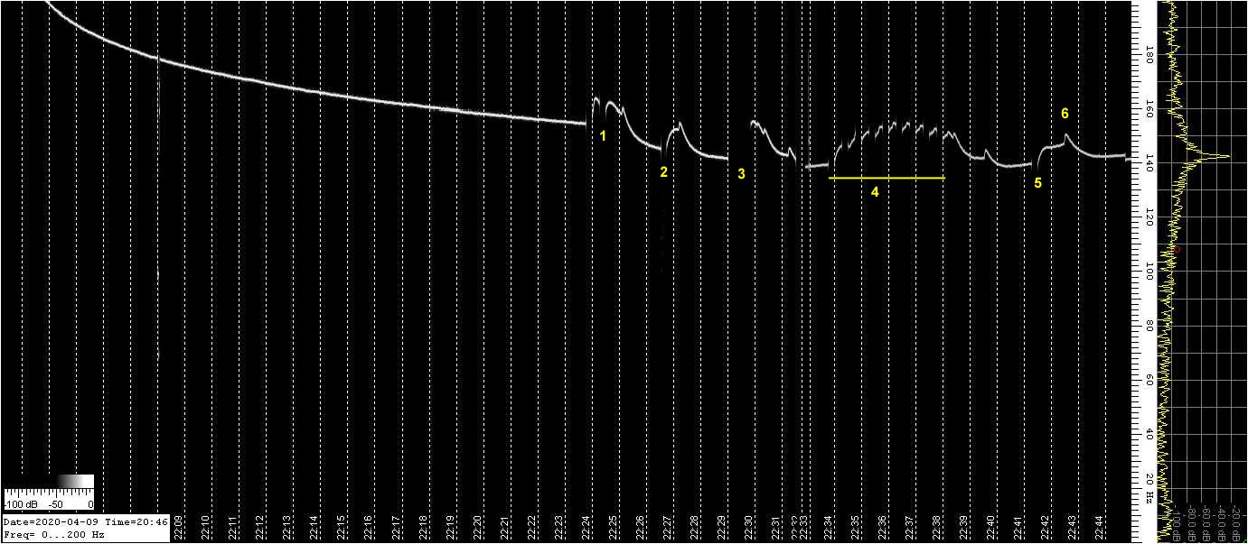
7100 receiving Rubidium reference with TX periods
The results were surprising. The graph shows that after transmission, the frequency has changed, which indicates that temperature is one of the probable causes of the drift. So far nothing special. The frequency on the chart goes up, which implies that the local oscillator (TCXO) of the 7100 goes down (the Rubidium reference is very accurate and its frequency can be regarded as fixed).
But just after switchover from TX to RX, it looks like the TCXO continues to drift for a short period and will start to “recover” a bit later. This behaviour cannot only be explained from temperature effects. I will return to that after the next spectrograms.
Position 3 was a one minute transmission and at position 4, a series of 15 second carriers was transmitted to simulate FT8. Position 5 again 15 seconds. At position 6, we see an unexplained sort of glitch.
Lime SDR
To rule out possible errors from the setup, A Lime SDR mini was hooked up. The Rubidium reference was connected to the Lime and the signal from the 7100 (connected to a dummy load) was leaking into the receiver. With a bit of fiddling, the levels were roughly the same and clearly visible. The audio from the SDR receiver (tuned to a bit below 430.0 and set to SSB) is shown on the spectrogram with the reference around 340 Hz and the 7100 a bit higher. Remember that this time, the frequencies are not inverted, as the Lime was receiving with USB.
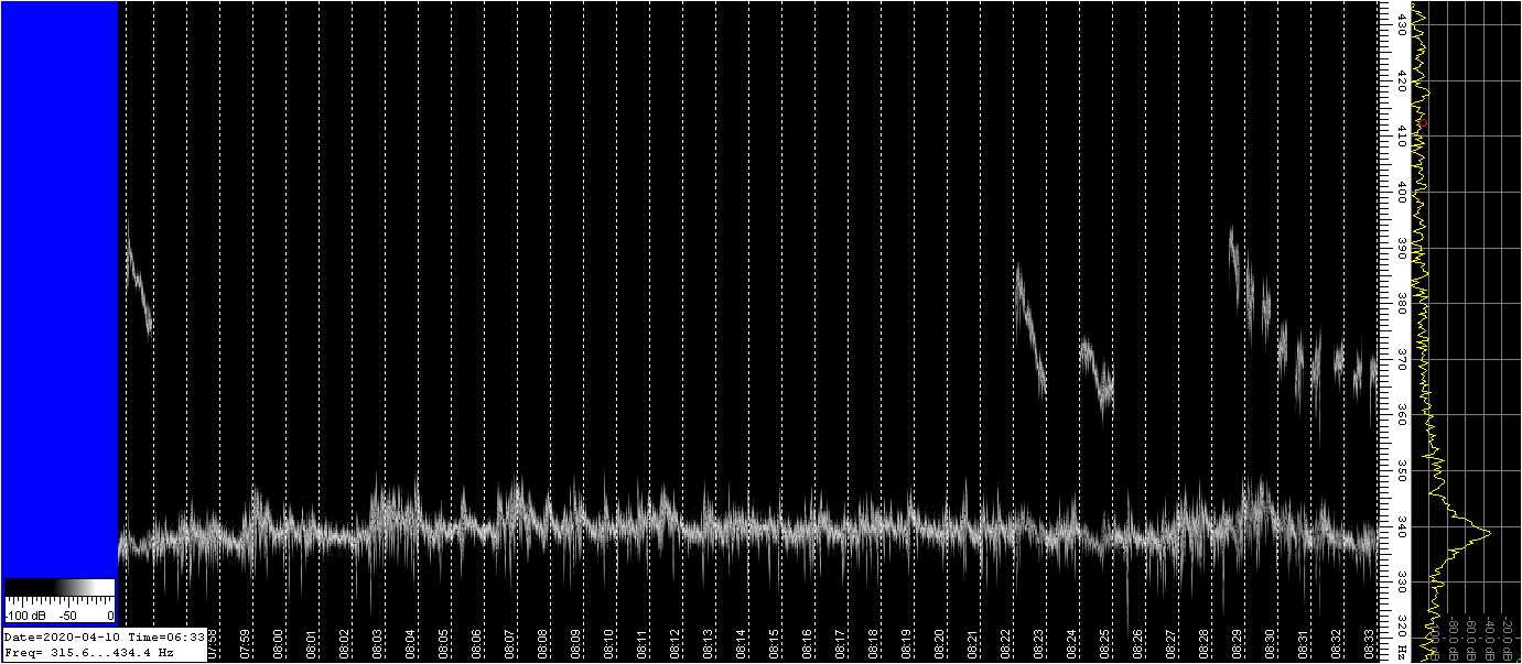
Lime SDR mini receiving the Rubidium reference and IC 7100
The accuracy and stability of the Lime was surprising, but it showed considerable phase noise. Nevertheless, I continued with the experiment. I had a coffee first, to make sure that the Lime did not drift away. A series of 1 minute transmissions showed the drift, which was quite considerable. Well within the 0.5 ppm specification, but not good enough for FT8.
I did not like the phase noise. To get rid of it, the Lime SDR was set to AM and to use the Rubidium reference as “carrier”. Tuned the 7100 bit above 430.0 so that only the difference (beat frequency) is shown. That worked out well.
430 .0 MHz reference as carrier, 7100 as sideband, AM demodulation
The signals were a lot clearer and the drift easier to estimate. Horizontal lines were drawn on the graph, which are 10 Hz apart. It looks like the drift is problematic for FT8, because it exceeds the 3 Hz limit. This implies that the FT8 message will,not be fully decoded and the forward error correction is needed to reconstruct the bit sequence. Because of the lost symbols, it will be less effective or even not decodable when the signal is weak.
Solutions?
I will have a further look into it and an update of this post can be expected.
I read reports about a modification of the Icom IC-9700 where the fan control is changed such that the fans keep operating continuously. This is one of the directions that I will try, maybe at first with an external fan. I will also check some voltages to make sure that the master oscillator supply is stable.
Some other modifications that I came across focus on improving the temperature stability in or around the TCXO.
So: to be continued!
Update 11 April 2020
Today, I had a closer look at things. The box was opened and it was soon clear, that temperature changes inside the unit are the main cause of the problem.
The supply voltage was checked and was stable, so that could be ruled out. Nevertheless, a slight improvement was seen when I connected the transceiver to the PS-126 power supply which I normally use for the IC-7600.
The master oscillator responds rather quick to temperature changes. If airflow is applied, it starts drifting and will try to compensate. As soon as the airflow is stopped, it drifts away again in the opposite direction and will slowly return to the equilibrium..
When transmitting, the fan kicks in and applies airflow to both the PA unit and the main unit (where the TCXO is found near the middle of it). The oscillator starts drifting and compensating. The fan speed is controlled and increases over time during transmit.
After switching back to RX, the fan keeps going for a short while and will then slow down in steps. The drift correlates with the fan speed and there you have it. The TCXO is exposed to temperature fluctuations because of the design of the transceiver. I doubt if it helps to keep the fan running all the time, because the heat from the PA will trickle down to the main board anyway, only could it be that the variations are smaller and perhaps somewhat slower.
Another option could be to divert the airflow from the TCXO, but that requires the main unit to be removed and I will check first how that can be done without damage.
Up to another update!
Update 12 April 2020
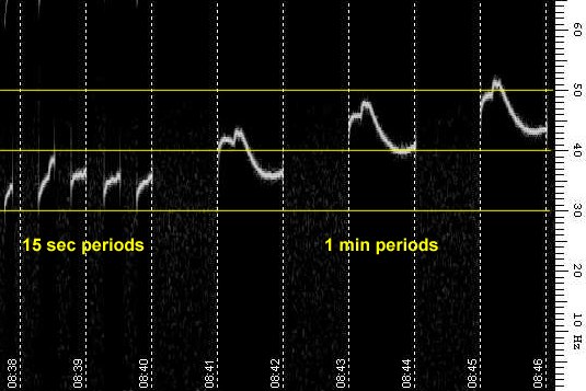
Assuming that changes of the airflow cause instability, I turned the unit upside down and removed the bottom cover. After warming up, I ran some FT8 transmissions to observe the behaviour. The following graphs show reception periods. When TXing, the waterfall is dark. Although it does not show the transmitted frequency changes, one gets an impression what is happening.
I set the timebase to a higher rate, to be able to see more detail during the RX periods of 15 sec. It can be seen that without the cover, the drift is less and it confirms the assumption that the changing airflow causes sudden changes. As soon as transmission starts, the fan starts running slow. After some time, the speed changes in steps. After changeover to RX, the fan keeps running at the same speed for a few seconds, after which it will slow down in steps to stop after roughly a minute. When the speed changes, the frequency changes suddenly and stabilises at a slower rate. The fan speed changes are marked on the graphs.
The first one shows the cover off/cover on difference, the second spectrogram shows the fan speed effects.
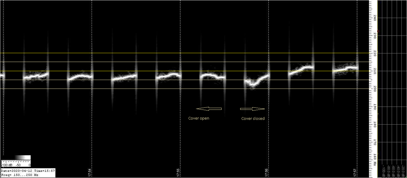
Effect of bottom cover open and closed
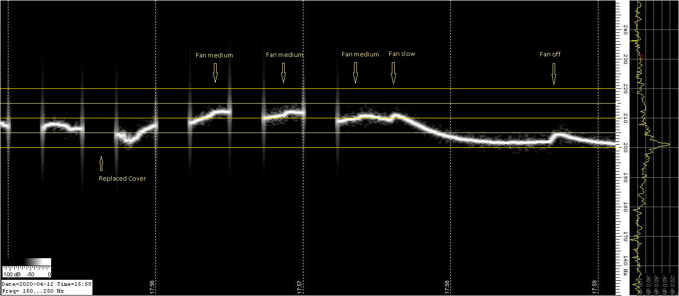
Fan speed effects
Leaving the cover off is not a very good idea, so one has to find a solution to stabilise the temperature of the oscillator, avoiding the sudden changes.
Some searching on the internet showed that the IC-9700 does seem to have similar problems. The TCXO is said to be the same as the one in the IC-9700 (a Murata TTS27VSC-A7 crystal oscillator) and one gets the impression that the stability “habits” of the IC-7100 resemble the IC-9700, that responds in a similar way to the fan activity.
Although Icom have changed the firmware of the 9700 to automatically recalibrate to a 10 MHz reference, the video below shows that the calibration lags the changes due to temperature changes when the fan starts, leading to a “swing” in the waterfall, which impairs decoding. The drift is over 20 Hz (on 432 MHz) which would imply that FT8 will not work altogether and I do not know if the AFC with modes like JT65 is able to compensate for such excessive drift.
Update 2025
Unfortunately, my 7100 was exposed to over voltage because a linear power supply failure. Repair appears to be quite a challenge. Two video’s were found on YouTube where a German bloke named Peter tries to repair. He ended up in replacing the main board, but tried to repair the main board afterwards and succeeded. Unfortunately, he does not provide details of which parts were replaced, leaving a lot of searching and guesswork.
I tried to follow the same “route” and found similar parts to be defect, like the 3.3 V regulator IC1001 (short circuit). It was isolated and 3.3 V was supplied to the junction between EP1002 and R1007 (H3R3V), but Q1001 does not switch on 3R3V and I am still puzzling. There was a problem with the power switch line which was possibly exposed to 14V (hmmm more than 14V) and I suspect Q1002 and/or Q1001 to be defect. It will be something for the coming winter period.