Trying to improve reception on 60 metres, many experiments followed, but nothing worked… It reminded me about Catweazle, a wizard in a TV series that ran during the early seventies.
Numerous receive antennas were tried, but none of them outperformed my dipole. Close to the dipole were a flag and a resonant loop. The flag is a terminated loop and is unidirectional. But just as with non resonant loops, the output is very low and it is very difficult to block common mode currents. I tested with portable receivers to make sure that the transmission line does not become part of the antenna. After weeks of experimenting and various walks round the house, I heard Catweazle say: “Nothing works…”.
Phased dipoles
Antenna patterns of horizontal dipoles at less than half a wavelength above ground show that the gain towards the horizon is low. They are basically skywarmers. My dipole is about 10 m AGL, so the gain towards the horizon is very low, but that is also true for interference from neighbouring sources.
Verticals can have better low angle radiation, but they pick up more noise from those angles as well. In the past, I tried a quarter wave vertical and it was very noisy.
About two weeks ago, I suddenly got the idea to try a second dipole, to be used with the main dipole in a phased configuration. Although the main antenna is fed with ladder line and tuner, I assumed that a divider/coupler between transceiver and tuner might work.
With phased antennas, one gets directivity and that could help to reduce noise.
My 7600 has a separate receive input and output, so it only took a simple CATV splitter to couple the antennas. I used a small tuner to vary the phase and an adjustable attenuator to align the amplitudes of the signals from both antennas.
The first impressions were promising. A variable phase shifter was needed and some searching led to some ideas. Just as I was putting something together, I stumbled upon a used MFJ-1026 QRM eliminator. It has some nice features, like a preamp with selectable gain.
Mutual coupling
The second dipole is only about 10 metres away from the main antenna and because of mutual coupling, the second antenna receives roughly about 5% of the power from the main antenna. The MFJ does not have a relay at the AUX input. A small lamp between antenna and preamplifier lights up when the power exceeds safe levels. I decided to modify the MFJ and add a relay between AUX input and the preamplifier.
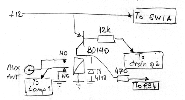
The circuit looks like this:
A picture shows the modification:
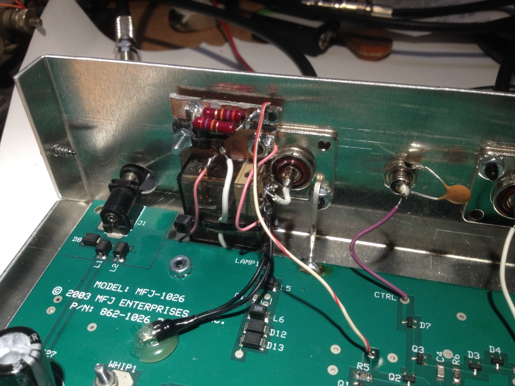
The phono jack for the AUX antenna was removed and that leaves room for the little board with the relay. Lamp 1 (to the preamp) was disconnected from the AUX antenna input and is now connected to the relay.
The white wire with the red stripes is the control line that connects to the drain of Q2. When receiving, that line is low and the relay is activated. When the unit is off, the AUX antenna is disconnected.
The 12 V is taken from the power on/off switch (pink wire to SW1A) and connected to the emitter of the BD140.
Not visible on the photo, but I connected the “Power” LED to the collector of the BD140 instead of the 12 V supply line. I wanted to have an indicator to check if the control (PTT) line from the transceiver is working correctly. R33 was removed (it is on the PCB pointing up and not connected) and a 470 Ohms resistor (“replacing R33”) connected to the collector of the BD140. When transmitting, the Power LED goes off. The LED is now on when the unit is active.
Results
On 60 metres, I get the best results with signals from the west. The second dipole is low, only about 3 metres above ground, about 10 metres west of the main dipole. Buildings obstruct signals from the east and signals are rather weak from that direction. It also seems that most QRM is from the east.
The video shows a comparison between compensation on and off. I tried to adjust it so that the signal was of equal strength when on or off. The S-meter does not get below S9 (incredible isn’t it?) but when the unit is on, the noise drops to about S6. Still rather strong, but the result is notable.
You can also watch the spectrum scope and waterfall, it clearly shows that the noise drops while the signal peaks are about the same.