A short while ago, I had problems with my antenna system on 20 metres. It took a while to trace the cause.
In 2015, I “restarted” amateur radio and put up a dipole for 60 metres. After a while, I decided to consider options to become QRV on other bands as well. I tried a Diamond multi band dipole. Yes, it worked surprisingly well, but there were some distinct disadvantages. The coils are not so XYL friendly and she did not like all the wires and coils hanging above the garden, which I can understand. Nowadays, the internet is full of ideas and after some reading I decided to go for a doublet with balanced feeder and tuner. I also remembered good signals on 60 m from those who are using this type of antenna.
One of the challenges was to feed the balanced line through the wall. At my QRL, we construct fibre optic networks and in some cases, micro-ducts are used, where single fibres are blown into the sub ducts. This fitted nicely in a hole of about 15 mm. The mini ducts keep the conductors apart. I had to select relatively thin wire to get an impedance that was not too low. The copper wires came from an electric motor.
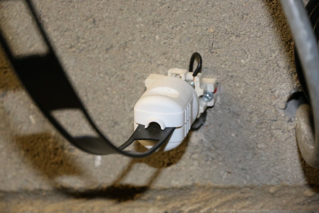
To be able to disconnect the antenna, in case of adverse weather, a mains socket and plug was used. As the HF band frequencies are low, discontinuities in the feedline are small compared to the wavelength. Even on 10 meters, we are talking about 10 degrees.
The impedance of the wall feed through was estimated at 300 Ohms and some calculation led to the conclusion that the idea should work.
Tracing the cause of the malfunction, I found that the wires in the socket had arced, because they were apparently too close, or maybe some dirt had played a role here. Separating the wires solved the problem, but I did not like the idea, so I decided to seek an alternative. Maybe the mini ducts were too small.
The QRL provided me some waste pieces of 75 Ohms CATV coax. This cable is used to feed distribution amplifiers and has low loss, because it is quite thick. The cable was taken apart and I only used the inner dielectric. This is essentially a PE tube with little dishes, also known as bamboo type. The little dishes hold the centre conductor. The original conductor was replaced with mains wire of about 1.3 mm diameter. The distance between the wires is about 13.5 mm. The impedance was estimated to be around 300 Ohms. With these dimensions, the power rating will more than adequate for my situation.
The calculations revealed that on 10 metres, the discontinuity is about 10 degrees and would transform 450 Ohms (the ladder line impedance) to about 425 Ohms, which would render a SWR of about 1:1.05. On lower frequencies, the loss is even less.
Of course, in the real world, one should investigate the impedance at the feed through, which is the result of the antenna impedance and the transformation along the 450 Ohms feeder. I also assume that the “mismatch” could be compensated for by the tuner, so I estimate the loss to be very limited.
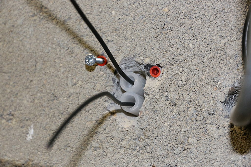
Ladder line feed through (inside)
Calculating the impedance
My curious nature led me to some calculation, trying to estimate the impedance across the feeder, both at the feed trough point and at the tuner end.
Two antenna analysis applications render rather different results for the antenna impedance/reactance, so it seems to be difficult to get reliable results. But one thing is clear: the standing waves cause both high voltages and strong currents along the line. I have seen values like 4 k Ohms and that means that one has to check carefully for possible problems. Even with 100 Watts, the peak voltage will be about 900 V, which means that you have to take that serious, both with respect to isolation and to protect it from touching.
The same it true for the currents, which can be very high and could cause malfunction as well.
So a doublet with tuner is a nice “all band antenna” but every coin has a flip side:-)